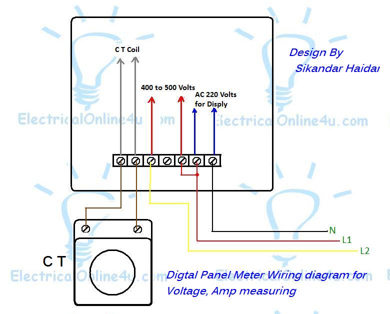
Meter Panel Wiring Diagram Victoria
A meter panel wiring diagram is an essential reference for electricians, builders, and homeowners in Victoria, Australia. It shows how electricity flows from the supply network into the main switchboard, through protective devices, and into the home’s circuits. Because Victoria follows strict electrical safety regulations, understanding the layout and function of a meter panel is crucial for safe installation, inspection, and maintenance.
What a Meter Panel Does
A meter panel (or meter box) serves three primary functions:
- Houses the electricity meter that records energy usage
- Contains the main switch and protective devices
- Acts as the central distribution point for all household circuits
In Victoria, meter panels must comply with:
- AS/NZS 3000 (Wiring Rules)
- Victorian Service & Installation Rules (VSIR)
- Requirements of local distributors such as Powercor, AusNet, Jemena, Citipower, and United Energy
Learn more:
- Victorian wiring rules
- Service and installation requirements
Key Components in a Victorian Meter Panel Wiring Diagram
1. Service Line (Incoming Supply)
Electricity enters the property via:
- Overhead service cable, or
- Underground consumer mains
These connect to the service fuse or network isolator, depending on the distributor.
Explore: consumer mains wiring
2. Meter (Single‑Phase or Three‑Phase)
The meter measures energy consumption.
Victoria commonly uses:
- Single‑phase 230V for homes
- Three‑phase 400V for large homes or commercial sites
Smart meters are standard across the state.
3. Main Switch
This is the primary isolation point for the entire installation.
Types include:
- Single‑phase main switch
- Three‑phase main switch
- Main switch for solar (if installed)
4. Main Earth & Neutral Links
These provide:
- Earthing connection
- MEN (Multiple Earthed Neutral) link
- Bonding to water/gas pipes where required
5. Circuit Breakers / RCDs / RCBOs
Modern Victorian switchboards must include:
- RCDs (Residual Current Devices) for personal protection
- RCBOs (combined RCD + circuit breaker) for individual circuits
- MCBs for overload and short‑circuit protection
Explore: RCD vs RCBO
Typical Wiring Flow (Text Diagram)
INCOMING SUPPLY (Service Line)
        |
        |----> Service Fuse / Network Isolator
        |
        |----> Meter (Smart Meter)
        |
        |----> Main Switch
        |
        |----> RCDs / RCBOs / MCBs
        |
        |----> Final Circuits (Lights, Power, Appliances)
Grounding:
Earth Stake → Earth Bar → MEN Link → Neutral Bar
This layout reflects the standard Victorian residential configuration.
Why Wiring Diagrams Matter in Victoria
A correct meter panel wiring diagram ensures:
- Compliance with Victorian electrical regulations
- Safe installation and maintenance
- Proper load distribution
- Compatibility with solar, EV chargers, and battery systems
- Faster inspections and approvals
Common Add‑Ons in Modern Victorian Meter Panels
- Solar PV isolators
- Solar meter or bi‑directional meter
- EV charger circuits
- Surge protection devices
- Main switch for inverter systems
Explore:
- Solar meter wiring
- EV charger installation basics
Final Thoughts
A meter panel wiring diagram in Victoria is more than a technical drawing — it’s a safety blueprint. Understanding the components and flow of electricity helps ensure compliance, reduce hazards, and support future upgrades like solar or EV charging. Whether you're an electrician, homeowner, or student, mastering this diagram is essential for working with Victorian electrical systems.
![[45+] 3 Phase Meter Panel Wiring Diagram](https://www.victronenergy.com/live/_media/energy-meters:schema_-_et340.png?w=600&tok=73b4ea)